
Driving a racecar is like dancing with a chainsaw
~Cale Yarborough
The steering wheel is one of the most integral components in an automobile considering the handling of the driver is directly associated with it, more so, while desigining a race car
Race car steering wheels are the most subtle yet most complex components when seen from a product designing point of view. They need to provide full accessibility and control over most of the car's units to the driver whilst ensuring that she/he doesn't strain her/his time or energy just trying to reach the right button
Also, there is the question of :
- At what angle will it be mounted ?
- How light but cost effective can it be made ?
- How can you customize the wheel for each driver ?
- How minimalistic yet effective can you make the wheel ?
- How strong can you make it to prevent under and oversteer at high speeds ?

Mulling over all these questions in mind, I was designing the 1st steering wheel for the final combustion car my institute motorsports team, Raftar Formula Racing (IIT Madras) would make, before migrating to an electric vehicle.
Our car's top speed at that time was 190kmph and the engine was powered by that of a KTM 390 superbike. So you can only imagine the vibrational load that the steering wheel would encounter under high speeds 🤯
The design
It took the team over 5 drawing iterations, 4 simulation loopbacks, 6 paddle shifter ideas and several other ways to make the wheel light, accessible and customizable
Whilst I was handling creation of the parts and the assembly, this project could not have been possible without the help and support from my team members Kulma, Ithan, Karthik, Shriram, Sahoo, Keshav, Abhiram and Sailesh

This project was carried out in 3 main phases :
- Designing the steering wheel plate
- Optimizing steering wheel plate design via simulations and stress analysis
- Paddle Shifter design
I started off by studying the previous steering wheel and initially just had the thought of optimizing it a bit but what resulted was something unexpected, arduous but astoundingly inspiring !
PHASE 1 : Designing the wheel plate
- As a reference, we studied RFR19 Steering Wheel and got the wheel plate outer dimensions that were preferred by the drivers
- Also, Formula Bharat 2021 latest rules were referred for compliance with Formula Student competition rules
- Saurav and I started off with a pretty basic designs and both branched out with different design concepts.
- I designed v1.1 and Sahoo designed v2. Both designs were reviewed in a meeting with a meet with the drivers.
V1.1 - A rough overview inspired from RFR19 wheel

- The drivers made thermocol models of both designs for understanding the ergonomics well. They approved and suggested optimizations on v1.1
Thermocol model test of v1.1

V1.3 - Holes and button positions changed

- As a result, Sahoo and I started working on optimizing the same design (design v1.1 ) by studying ergonomics of several other teams’ , companies’ and other wheel manufacturers’ designs.
- After design v1.6, a decision was made to bend the wheel towards the driver for better force distribution. This was the most crucial and most unexplored design descision we took that was the single best feature to optimize the weight to strength ratio of the steering wheel
- v1.7 involved a uniform bend across the surface of the steering wheel. It was rejected as a design as it made attaching the wheel to the quick release quite a problem
- v1.8 involved a flat midsection and bending the wheel at the edges

- From this point on, I proceeded further with designing paddle shifters and the associated actuation while Saurav proceeded with performing simulations on the steering wheel plate to study force distribution, safety factor and topology optimization.
PHASE 2 : Optimizing the wheel plate
This majorly did 2 things
- Made the steering wheel light
- Made the steering wheel strong
The mastermind that is Saurav Sahoo....
- The plate was decided to have 5 layers of Carbon Fiber on either side of an Aluminium Honeycomb core.
- The boundary conditions are a fixed support where it's attached to the quick release, and the forces applied were F1:155 N(y), -269 N(z) and F2: 217 N(y), -376 N(z) and a moment of 88 N-m.

- Viability of bending the plate was checked ergonomically, but it still had to be checked mechanically.
- So a comparison test for Safety Factor and Equivalent Stress distribution was done between a flat plate and a curved plate
- It was found that the Inverse Reserve Factor (more this value, less the safety factor ) decreased and so did the Maximum Equivalent Stress

- So an ACP simulation was done on the partial bent plate decided on v1.8 and the results were compiled and compared to the results of the RFR 19 Steering Wheel.
- The maximum deformation obtained was 2.129 mm down from 2.94 mm in RFR 19 Steering Wheel
- The IRF obtained was 0.945, which deems it safe to use
PHASE 3 : Paddle Shifters design
This was the most gruelling and difficult design part. We had to use the least number of components whilst making it all work like clockwork for the driver using it
We chose this as a component because of the driver comfort it would give as opposed to stretching out thumbs to hit the buttons to shift up and down
We went through so many models and iterations that it was pretty surprising when we decided to scrap all that we'd seen and put up our own simple, unique design as the solution to it all
- Initially, I, was assigned the task of improving upon Shriram’s design. I managed to change the shape of paddle shifter to a more ergonomically optimized one and made changes to present actuation to make this new paddle shifter design compliant with the newly designed wheel plate
Initial design

However, this was rejected due to 3 main reasons :
- It is difficult to manufacture.
- It didn't seem right to actuate 2 shifters with the same spring.
- This component was monolithic so it would be difficult to dis-assemble for improvement or repair purposes.
I was now assigned the task of coming up with my own idea for the entire design and actuation of paddle shifter.
- After some research, I came across a YouTube video that showed the entire process of making paddle shifter using some small parts (CADs were available as STL files) and regular linear springs’
My version of paddle shifter and wheel plate inspired from YouTube

I tried to copy this design to a great extent but finally it was rejected due to the following reasons :
- Too many parts were involved in the actuation and there was no need to involve so many moving parts and attach them when we could come up with lesser, static parts
- The parts would have been too complicated to manufacture
- Thus, after much brainstorming with Shriram and Karthik, I now started working on a simpler design that would comply with the current assembly (new wheel plate + quick release), involve actuation buttons and contain a lesser number of parts that were easy to manufacture.
- This phase involved some trial and error to make the parts as small, as simple and as less in number as possible
Eg: The support boxes dimensions were reduced from 53*39 mm to 46*31 mm

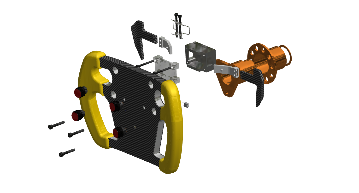
- We were able to finally arrive at a working model of the steering wheel assembly involving these parts :
| PART | SPECS | FUNCTION |
|---|---|---|
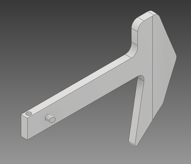
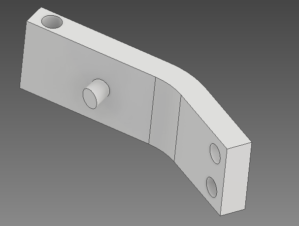
Paddle Shifter |
A 66 mm high, 92 mm long paddle shifter with a oblique cylindrical protrusion to actuate the switch 2 paddle shifters on either side of wheel plate center for upshift (Right) and downshift (Left). |
Follow an arc-like motion constrained by the torsional spring. When pulled towards oneself, the driver forces the paddle shifter (against the spring force) to actuate the switch and thus, shift gears |
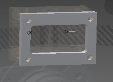
Mounting Plate |
A 46x31 mm plate with protruding 3x27 mm screws. Houses actuation switches on its surface | Mounting the support box onto the wheel plate. The paddle shifter hits these actuation switches to change gears |
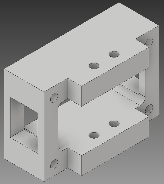
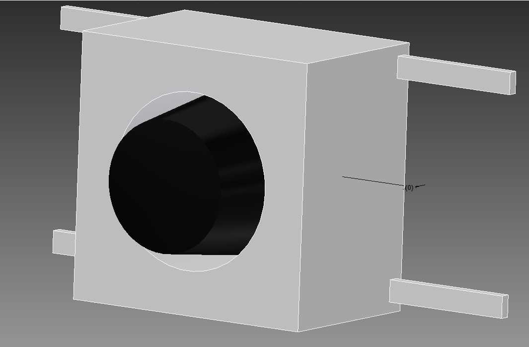
Support Box |
A 46x31 mm cuboid with 2 3mm holes for rotation axis of paddle shifters. It also has 4 other 3 mm holes for mounting |
Provide a space for the motion of the paddle shifter along with axes of rotation. Mount the actuation on the mounting plate |
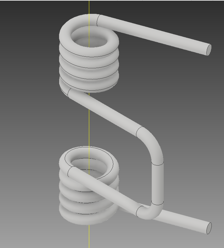
Torsional Spring |
A dual coiled 18 mm long spring. Each coil has 4mm diameter and 1mm cross-section diameter |
Constrains motion of paddle shifter through it’s resistive spring force |
Actuating Switch |
A 6x6x8mm switch with a 4mm wide button | Gets actuated by protrusion on paddle shifter and converts actuation into an electrical signal that will stimulate a gear shift |
Back Lid |
A 46x31mm rectangular plate | Protects the components inside the support box |
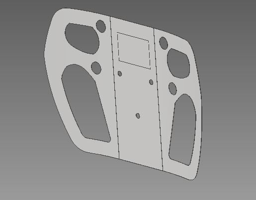
Wheel Plate |
A 220x140 mm wheel plate slightly curved at the edges. Houses 4 buttons. Houses 3 holes for mounting quick release |
Turning the tires. Actuation of upshift/downshift, brake, accelerator |
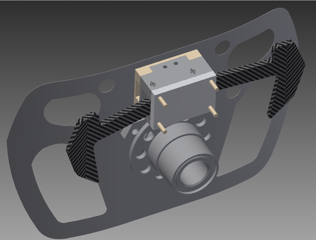
- Compact fitting and motion of various parts involved without any overlaps. Enough space has been provided to mount the PCB and the wiring accompanying it
- Smaller, lesser and functionally optimized parts protected well
- Slight optimizations (eg: Bending of wheel plate, positioning of buttons, shape of paddle shifters)
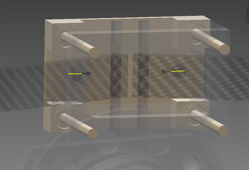
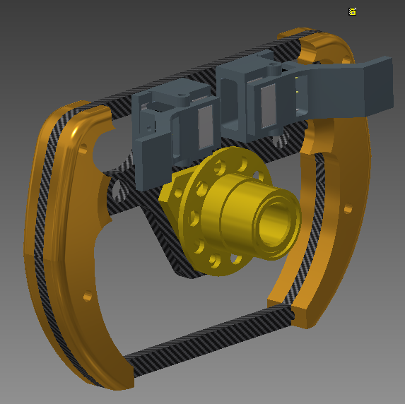
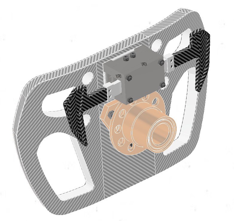
An enhanced view of the paddle shifter assembly

- Lastly, as an afterthought we disassembled the paddle shifter itself into 2 parts for better customizability for each driver's hand :
| Part | Function |
|---|---|
Functional |
Actuates the button in a controlled fashion due to spring constraint |
Interactive |
The customizable, personalized part interacting with the driver's hand and mounted onto the functional part |

Afterthought
That's how we came up with the design of the coolest,cheapest and most comfortable and customizable steering wheel design for the drivers of the RFR21 car that we virtually built and simulated, owing to the COVID19 pandemic in 2021 that had us all under lockdown.
It was one heck of a journey designing this beaut, right from sketching out plate diagrams, making thermocol models, brainstorming designs and even arguing to no end about the minute tweaks each design iteration would bring.💪
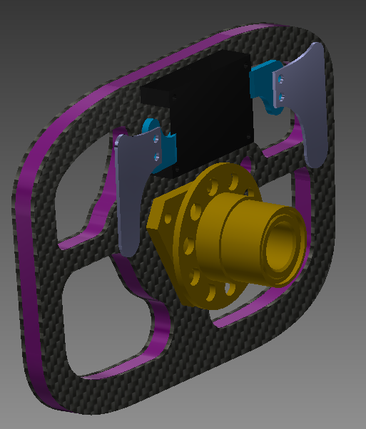
The rough mockup design

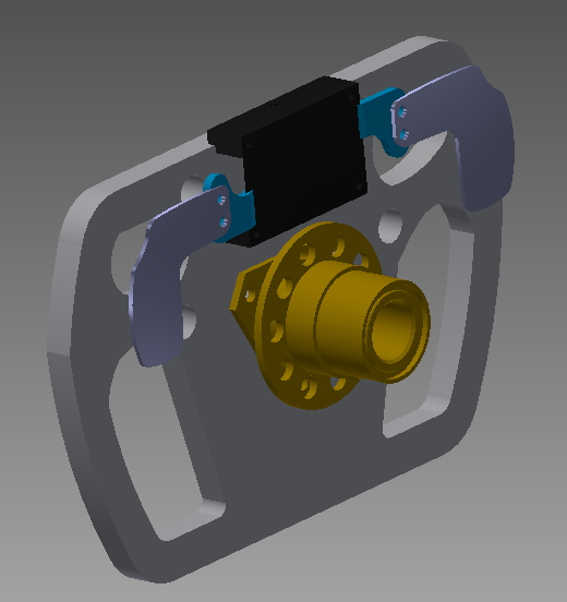
The final design

This final image is something that always puts a smile on each of the associated project member's face and even got applauded by the judges in the national level Formula Bharat as a simplistic, unique approach, unexplored before🔥
Next year, we go on to build our 1st electric vehicle, RFR22 and boy is that one gonna be an even more thrilling journey with all the chassis and powertrain being designed from scratch !🚀
I hope you enjoyed reading this blog and I'll see you next time with a high performance electric racecar steering wheel ......